Examples
Example of project can be found in examples folder.
For more usecases check also tests folder.
spi
An example shows how to create a simple spi interface.
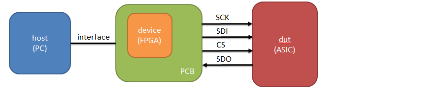
Instantiate a verilog spi module in the firmware verilog code.
localparam SPI_BASEADDR = 32'h1000;
localparam SPI_HIGHADDR = 32'h1FFF;

spi
#(
    .BASEADDR(SPI_BASEADDR),
    .HIGHADDR(SPI_HIGHADDR),
    .MEM_BYTES(4)
)  i_spi
(
    .BUS_CLK(BUS_CLK),
    .BUS_RST(BUS_RST),
    .BUS_ADD(BUS_ADD),
    .BUS_DATA(BUS_DATA),
    .BUS_RD(BUS_RD),
    .BUS_WR(BUS_WR),

    .SPI_CLK(SPI_CLK),

    .SCLK(SCLK),
    .SDI(SDI),
    .SDO(SDO),
    .SEN(SEN),
    .SLD(SLD)
);
Create a configuration file.
transfer_layer:
  - name  : intf
    type  : SiSim

hw_drivers:
  - name      : spi
    type      : spi
    interface : intf
    base_addr : 0x1000
    mem_bytes : 2

  - name        : CNT
    type        : StdRegister
    hw_driver   : spi
    size        : 16
    fields:
      - name    : EN
        size    : 1
        offset  : 15
      - name    : OUT
        size    : 15
        offset  : 14
Write control program.
dut = Dut('spi.yaml')
dut.init()

dut['CNT']['EN'] = 1
dut['CNT']['OUT'] = 0x00f0
dut['CNT'].write()
dut['CNT'].start()

while not dut['CNT'].is_ready():
    pass
Result of simulation:
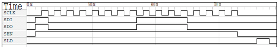
A workin example can be seen in tests/test_SimSpi.py.
gpio
TBD.